

How to Draw Terrain (Corner) Coordinates with AutoCAD?
If you do not have the dwg file of the land you will work on, it is possible to obtain the contours of the land by entering the corner coordinates in the Application Sketch you will receive from TKGM or Survey and Cadastre Engineering Offices.
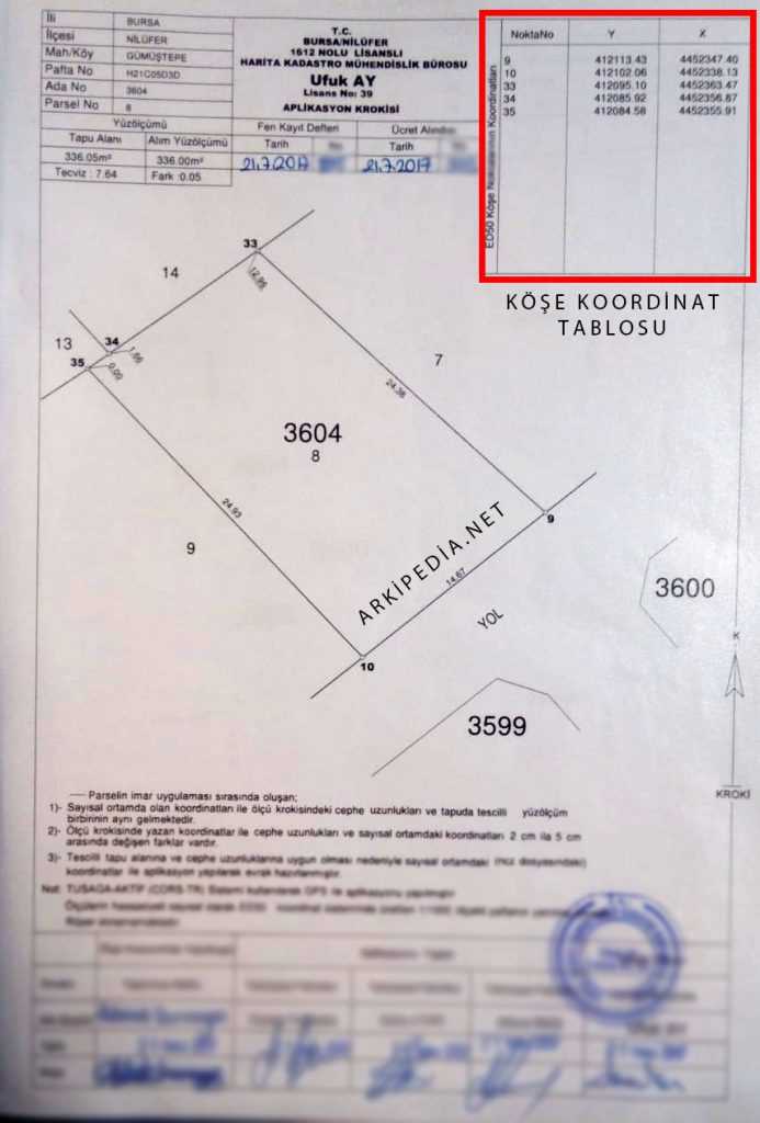
There is something you need to pay attention to when entering land coordinates. We need to use the coordinates in the table in the Application Sketch in reverse order.
The Y value will be our X value and the X value will be our Y value. It is important that we make our entries this way.
When you access the AutoCAD interface, let’s enter the land coordinates on the application sketch using the “point” command.
How to Use AutoCAD Point Command?
- Let’s type the point command and press enter.
- We will be asked to enter the coordinates containing the X and Y planes.
- For example, let’s enter the values (X) 412113.43 and (Y) 4452347.40.
- We write 412113.43 in the box, put a comma, then write the other value, 4452347.40, and press enter.
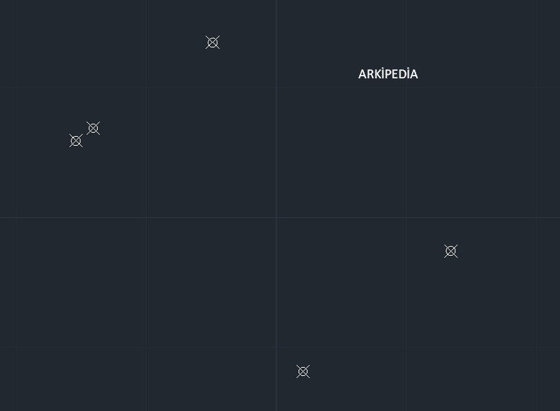
- Congratulations, you have successfully created the first corner coordinate.
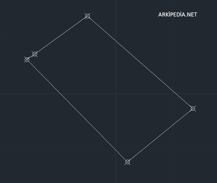
We repeat the same process for other points. When all the points are created, you will get the result as in the image below.
After your points are created, all you have to do is to obtain the outer border of the land by connecting the points with the “polyline” tool.
Congratulations, you created the corner points using the land coordinates and then connected them with the line to obtain the outline of your land. Your design will be waiting for you in the next process, may your pen be strong…